
Hey Everyone.
This started as a project where I built my own collective with the long term goal of selling a few. With university and work time constraints it was finally finished but I definitely didnt have time in the near future to make a product of a quality/finish I would be happy to sell. Therefor, because the Flight Sim community and in particular the guys at the 229th I thought I would share how I made it.
This is a DIY project with the idea in mind that anyone with a drill, hacksaw, soldering iron and internet connection can build. I had originally built it with a few joins using epoxy but after about 6 months use they started to slip. I then got a friend to do a quick 2 minute weld on the one join and now its as strong as ever.
It does require a few semi expensive parts though (if you want it to look pretty). The 4 critical parts are:
– the hat switch with the coolie hat on it, ($20 AUD)
– black anodized panels that the switches are mounted to, ($60 AUD laser engraved, much cheaper if people buy together)
– 3D printed head unit that the panels are mounted to. ($50 to $100 depending on source and quality)
– Micro controller that interfaces with your computer ($30 if you are willing to upload code (which i provide) to a Teensy board, $50 plus for leo bodnar alternative)
THE CATCH: I spent many hours teaching myself C++ code and AutoCAD to complete the files I have attached for you to use. If you use my files please consider making a small donation using the Paypal buttons further down this page.
PT 1 – Parts
Parts:
Aluminium
For the following aluminium parts just go to your local supplier, For Victoria, Australia I used these guys: Aluminium supplier
– Aluminium rod 10mm OD * 120mm (needs to be solid, not tubing)
– Aluminium tube 25mm OD 3mm wall 500mm long
– Aluminium tube 32mm OD 3mm wall 130mm long
– Aluminium U channel W 100mm * H 50mm * T 6mm 160mm long (3mm thickness will work as well, just need to be careful in construction. I was using interference fit bolts so went with 6mm to make sure they held)
– Aluminium right angle W 25mm * H 25mm * T 1.6mm 300mm long (will be cut down to numerous smaller parts as mounting brackets etc)
– KP000 10mm self aligning pillow block 2 10mm pillow block or 2 * KP000 Pillow block


Laser etched button panels:
**– 1.6mm to 2mm thick black anodized aluminium. **PDF FILE for etching company (cuts are in red, etching is in black, there is also external measurements)These are expensive in 1 off runs; for the 2 panels was $62 AUD the cheapest I found from these great guys in oz who would also do a run of 5 for roughly $30 per set. I got quotes from about 15 places and most wanted over $120 AUD just for one set.

3D printed collective head boxes (panels attached to front):
– The DOWNLOAD consists of two .stl files; one for the top box and one for the main box. The .stl files are a format designed for 3D printing software that can be used by pretty much every printing company world wide. To view the stl files you can download an stl viewer here or from my own server here


Buttons:
Buttons confused me for a bit with throws and poles, momentary vs latched etc but no need to worry. For nomenclatures sake a button position in brackets means momentary (ie will spring back to the center position when released) while not in brackets means latched (ie, will stay in position and would have to be physically shifted back to center position).
Eg (On) – Off – On means (momentary ON) – center – latched ON
– (On)-Off-(On) with flat toggle * 1 (on)-off-(on) toggle
– On – On with round toggle * 1 On-On (also known as on-none-on since it doesnt have a center position)
– On – Off – On with round toggle * 2 On-Off-On toggle
– push button (mom) * 1 Mom push button (this simulates the throttle stop release, it wont actually physically lock the twist throttle but will engage the button in game)
4 way button with china hat
**There are a few ways to do this. The switch below is a grayhill 04A which is actually used in FAA approved joysticks, I found it much better to use something of this size and quality compared to weak little ones.
1. in US, buy whole thing together here **4way china hat or from (infinity) here using his accessories order form a little bit down the page. He is a good guy with an awesome business that is good to support
2. in EU, buy whole thing here 4way china hat EU
**3. in AU buy the whole thing together from either of the above or:
get just the switch from here grayhill 04A 4way button** and order just the china hat from infinity by putting a note in the accessory order form (he does it even though its not on the list, they are $1.05 each hat).
Other Electronics:
– Teensy 3.1 teensy 3.1 This a micro controller that will interface with your computer via USB. Arduino’s can be used as well but I like the smaller form factor of the teensy. A Leo bodnar board is probably the easiest but being a NERD I enjoyed programming the teensy from scratch. Dont worry I will include the code.
– A1324LUA-T Hall effect sensor A1324LUA sensor the A1325 or A1326 from the same family can also be used but they aren’t as sensitive. This will be used as the primary sensor for the collective so its good not to skimp.
– 10k LINEAR potentiometer 10k 9mm Lin pot (need a smaller one like this 9mm one, the 16mm and bigger are to big for what we need)
– Protoboard protoboard
– 16 core rainbow ribbon 1m ribbon cable
– 555mm rare earth magnet 2 rare earth magnets(its not a bad idea to get extra, these things are strong and disappear when stuck to tools etc, i also wouldn’t go any smaller)
PT 2 – Design
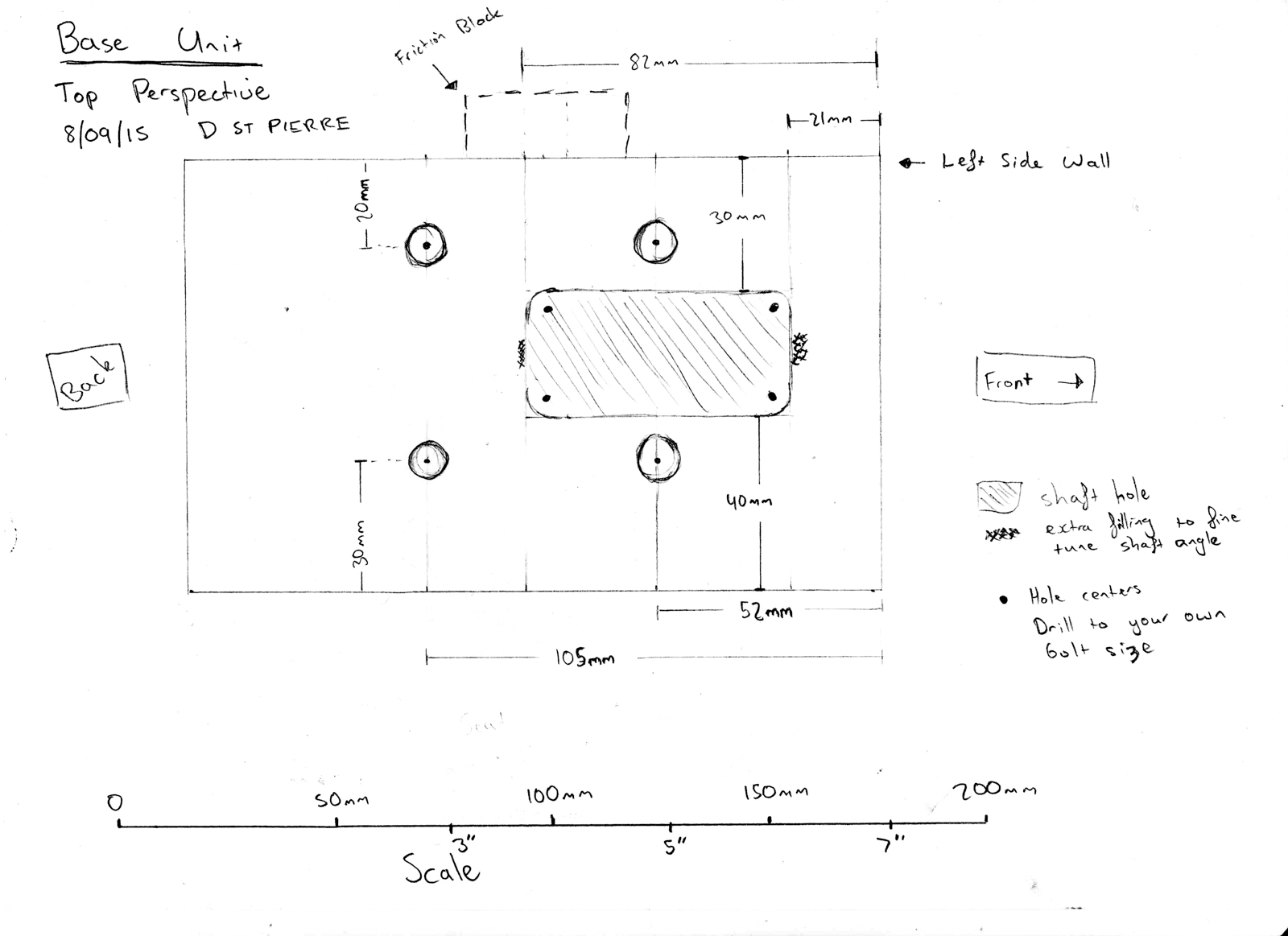
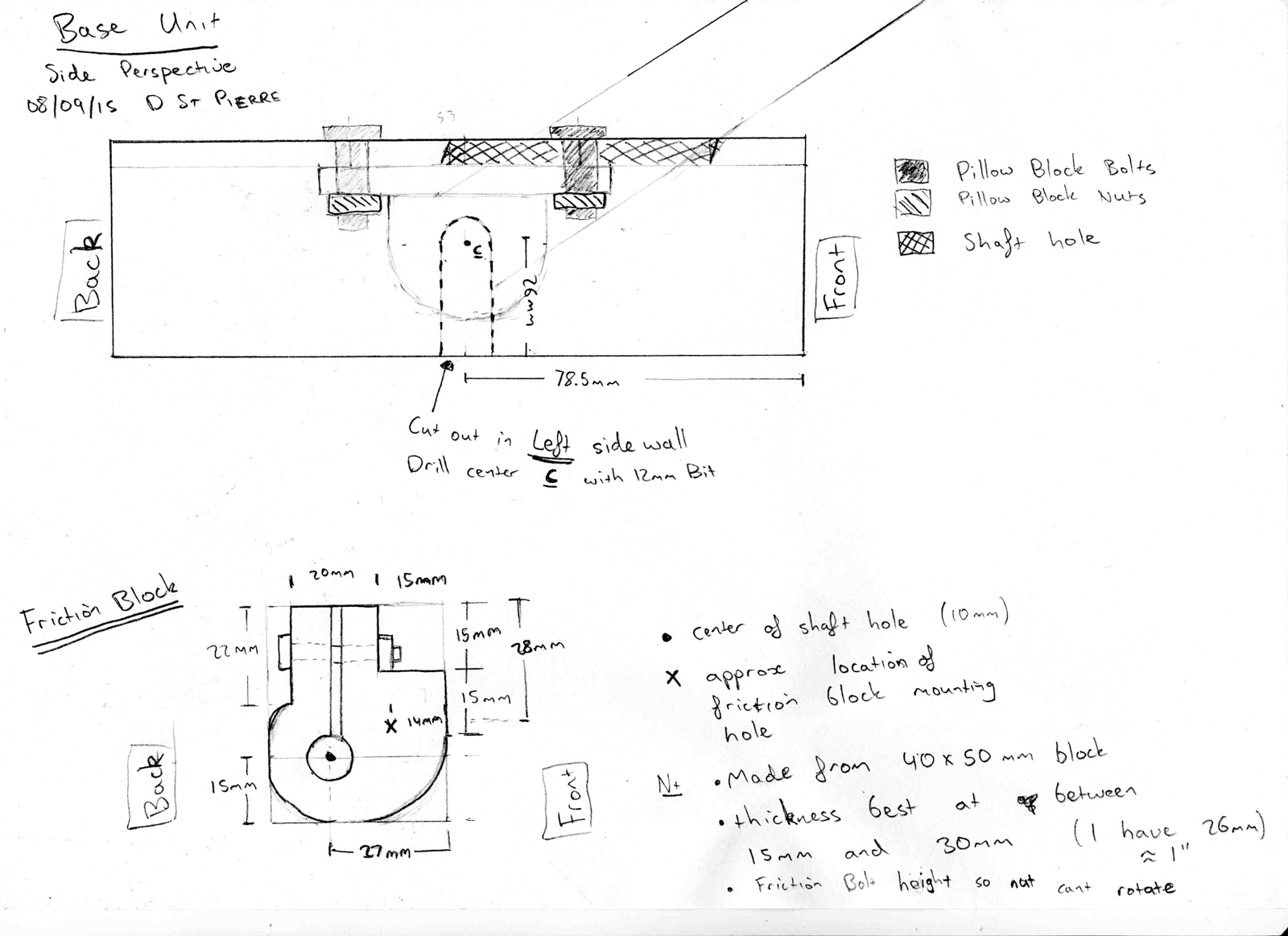
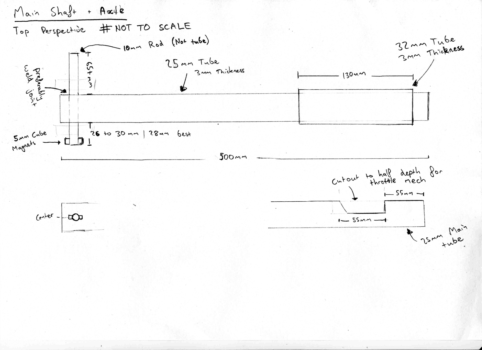
Attached are the plans for base unit, mains shaft and friction block. The measurements are based on using KP000 pillow blocks – spec sheet also attached.
As you will see I dont give a diameter for the holes in the top of the base unit; you should always pilot first with a small drill bit like 2mm and then expand out to the size you need for your bolts.
With the Main shaft hole (marked by angle hatch) I drilled the 4 corners out starting at 2mm and then going out to the biggest drill size my chuck could take. Hence I have marked the hole centers at the corners shifted inside. The fore-aft relationship between the Main shaft hole and the pillow block holes is critical for determining the angular range of motion for the main shaft. What is presented here is slightly conservative and the Main shaft hole can be filled out to refine the angle limits.
Also special attention needs to be payed to which side the cut out is made to allow the axle to run out into the friction block, The plans are drawn from a right perspective but the cutout goes on the LEFT side.
AS ALWAYS MEASURE ONCE CUT TWICE ![]() all images can be clicked on for full size
all images can be clicked on for full size
Reference Images
 Collective-01
 Collective-02
 Collective-03
 Collective-04
 Collective-05
 Collective-06
 Collective-07
 Collective-08
 Collective-09
 Collective-10
 Collective-11
 Collective-12
 Collective-13
 Collective-14
 Collective-15
 Collective-16


REFERENCE MATERIAL
Using a universal joint and hall effect sensors to make a joystick – pdf guide by Julian – original
DIY hall sensor mechanism thread – thread link by f15 sim